1.1.4 Solar Charging
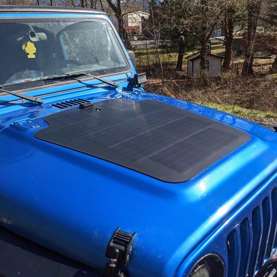
Type: Flexible Monocrystalline Solar Panel
Model: Cascadia 4x4 80W Hood Solar Panel (VSS System for TJ/LJ 2003-2006)
Manufacturer: Cascadia 4x4
Product Page: Cascadia 4x4 VSS System
Note: VSS System includes MPPT controller, but using BCDC's built-in solar MPPT instead (panel only from VSS kit)
Electrical Specifications
Power Output:
- Maximum Power @ STC: 80W
- Optimum Operating Voltage (Vmp): 40.1V
- Optimum Operating Current (Imp): 1.95A
- Open Circuit Voltage (Voc): 46.8V
- Short Circuit Current (Isc): 2.23A
BCDC Compatibility: Voc 46.8V within BCDC solar input range (9-48V) at STC (25°C)
Cold Weather Voc
Solar panel Voc increases in cold temperatures (~0.35%/°C). At 0°F (-18°C), Voc may reach ~53V, exceeding BCDC's 48V limit. The BCDC Alpha has overvoltage protection - soft fault (LED warning) progressing to hard fault as voltage increases. See Optional Overvoltage Protection below for automatic disconnect solution.
Physical Specifications
- Dimensions: 68 × 66 × 5 cm (27 × 26 × 2 in)
- Weight: 2.6 kg (5.7 lb)
- Top Sheet Material: ETFE (fluoropolymer)
- Mounting Method: SolarClasp™ adhesive system
- Connector Type: MC4 (standard solar connectors)
- Cable Length: 190 cm (74.8 in)
- Mounting: Permanently adhered to hood surface
- Connection: Wired to BCDC Alpha 50 solar input
Wiring
Solar Panel Connections:
- Positive (+): Panel output → BCDC Alpha 50 solar input positive terminal
- Negative (-): Panel output → Chassis ground (NOT to BCDC negative)
- Wire Gauge: 10 AWG minimum (for 2.23A Isc with safety margin)
- Routing: Hood → Firewall → BCDC location in passenger rear wheel well
- Maximum Current: 2.23A (Isc) - well within BCDC solar input capacity
VSS System Note: VSS kit includes standalone MPPT controller - not used. BCDC has built-in MPPT on solar input, providing Green Power Priority and unified charge control.
Important: Solar negative connects to chassis ground per REDARC specifications. The BCDC requires a common ground system where all batteries and components share the same ground reference (vehicle chassis).
Function
80W panel maintains AUX battery during extended stops via BCDC solar input. Full sun panel output at optimal conditions: 80W (1.95A @ 40V), variable in partial sun/clouds.
Panel-side vs battery-side current: The 1.95A figure is panel-side current at the panel's ~40V operating voltage (40V × 1.95A ≈ 78W). The BCDC's MPPT steps that down to battery charge voltage: 78W ÷ ~13.4V ≈ ~5.8A to the AUX battery.
BCDC Green Power Priority: Solar input used first when available, alternator supplements to reach 50A total charging current. Battery-side contribution by condition:
- Full sun: ~5.8A (reduces alternator load from 50A to ~44A)
- Partial sun: Variable, proportional to available irradiance
- Overcast/Night: 0A (BCDC uses alternator only)
See BCDC Alpha 50 for complete charging system details.
Installation: See Section 1 Installation Checklist
Critical: Verify polarity before connection - reverse polarity damages BCDC.
Optional Overvoltage Protection
To automatically disconnect the solar panel when cold-weather Voc exceeds the BCDC's 48V limit, install an adjustable overvoltage disconnect module.
Recommended Component
Over/Under Voltage Protection Relay Module
- Type: Compact PCB module with adjustable thresholds
- Example: Amazon DC Over/Under Voltage Relay Module (~$15-25)
- Voltage Range: DC 36V version has overvoltage adjustment range of 39-51V
- Delay: Adjustable 0.1-15s (prevents nuisance trips from brief voltage spikes)
- Contacts: Relay with NO/NC contacts, rated 10A (solar is only 2.2A)
- Power: Self-powered from monitored circuit (no separate 12V tap needed)
- Size: Compact (~2" x 2") - mount near BCDC or in small enclosure
Wiring Diagram
Solar Panel (+) ──┬── Voltage Module Sense Input
                  │
                  └── Voltage Module Relay (NC) ──── BCDC Solar Input (+)

Solar Panel (-) ────────────────────────────────── Chassis Ground

Voltage Module Power: Self-powered from solar panel voltage
Configuration
| Setting | Value | Purpose |
|---|---|---|
| Overvoltage Threshold | 47V | Disconnect before BCDC 48V limit |
| Undervoltage Threshold | Disabled or 10V | Don't disconnect at low voltage |
| Reconnect Hysteresis | ~3V (44V reconnect) | Prevent rapid cycling |
| Trip Delay | 1-2 seconds | Ignore brief voltage spikes |
Operation
- Normal conditions (Voc < 47V): Relay closed, solar charges normally
- Cold weather (Voc > 47V): Relay opens, disconnects solar from BCDC
- Panel warms up (Voc drops < 44V): Relay closes, charging resumes automatically
- BCDC protected: Never sees voltage above 47V
Installation Notes
- Mount module in weatherproof location (near BCDC in passenger rear wheel well, or sealed enclosure)
- Use MC4 inline connectors for easy solar disconnect during installation
- Consider conformal coating on PCB for moisture protection
- Test threshold settings before final installation
Alternative: Series Diode Voltage Drop
For a passive (no electronics) solution, install 4-5 series rectifier diodes (10A10 type) in the solar positive line:
- Voltage drop: ~0.7V per diode × 5 = 3.5V permanent drop
- Result: Reduces 53V cold Voc to ~49.5V (still marginal)
- Cons: Permanent ~8% power loss, generates heat
- Pros: No moving parts, no adjustment needed
Recommendation: The relay module is preferred - no power loss during normal operation and provides automatic protection only when needed.
Outstanding Items
High (3)
- JL Audio amp feed: 100A CB exceeds 4 AWG ampacity (95A @ 20°C) (#149) — The amp's battery feed is 4 AWG (95A continuous @ 20°C per the project reference table) protected by a 100A CB. The amp's internal 80A fuse is downstream and does not protect the battery-to-amp run against a chafe/short. This violates the project's "CB protects the wire" rule and is NOT covered by STANDARDS-EXCEPTIONS (which only sanctions the SwitchPros/SafetyHub 150A-on-2-AWG case).
- START+ auxiliary distribution busbar + breakers for relocated fan / iBooster / TCU (#135) — Relocating the radiator fan, iBooster, and TCU from the PMU to START-battery-direct adds three breaker-protected feeds. All three loads are forward (engine bay / transmission) while the START battery is rear, so the chosen architecture mirrors the AUX forward-feed pattern: a single master-protected feed forward to an engine-bay busbar rather than three long runs or ~9 stacked lugs on the battery post.
- Dakota Digital Panel Mounting (#39) — HDPE sheet dimensions and location for the Dakota Digital panel.
📋 Medium (10)
- SwitchPros Output Wire Lengths (#107) — Wire lengths for the 12 SwitchPros SP-1200 output circuits (front/cabin/rear/roof fan-out from the firewall) are currently 'Various / TBD'. Determine once final load mounting locations are fixed.
- Radio Ground Routing (#82) — Path for 14 AWG ground wires from GMRS / Intercom (dashboard) to START battery negative (driver rear wheel well) - direct grounds required for RF noise isolation
- BODY PDU Metri-Pack Pinout (#69) — J301-J306 connector pinout (military TM or reverse engineering)
- Alternator Voltage Regulator Set Point (#68) — Verify 14.2-14.4V for AGM batteries
- Alternator Output Terminal Size (#67) — Terminal size for 1/0 AWG lug selection
- RF Power Grommet Location (#66) — Grommet 6 location near battery for radio power
- Roof/Roll Bar Routing (#64) — Light bars, dome lights
- Cab to Cargo Routing (#63) — Rear lights, compressor, lockers
- Dash to Console Routing (#62) — Switch panels, USB, radio
- Firewall Grommet Circuits (#61) — Complete wire bundle lists
📝 Low (1)
- AUX battery− chassis-bond (rear frame rail) peak return current (#124) — Peak current through the AUX battery− → rear frame rail 2/0 chassis bond needs a proper derivation.
🔍 Verify (2)
- ARB compressor feed length: reconcile 8/10/12 ft and measure (#154) — Three different lengths are documented for the SafetyHub → ARB twin compressor feed: ~8 ft (wire-distance reference), ~10 ft (harness inventory H6), ~12 ft (SafetyHub circuit table). The SafetyHub is in the passenger rear wheel well and the compressor under the seat, so the spread doesn't change the 6 AWG sizing materially, but the figure should be measured and unified across the three files.
- Measured cable distances: START battery → relocated radiator fan / iBooster / TCU (#136) — The radiator fan, iBooster main, and TCU now feed from the START+ forward distribution busbar (engine bay) via a single master feed from the START battery (driver rear wheel well). Provisional gauges:
Build Tasks
- Order overvoltage protection relay module (DC 36V version, ~$15-25)
- Determine mounting location for voltage module (near BCDC or inline with solar wiring)
- Test and configure voltage thresholds before final installation (47V disconnect, 44V reconnect)