2.6 Radiator Fan
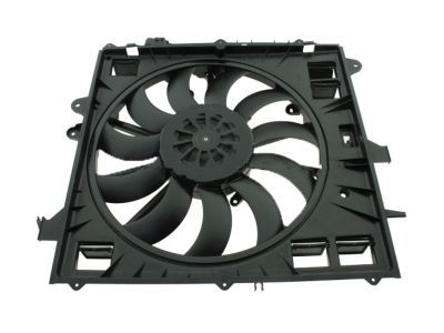
Type: Electric radiator fan
Model: GM 84100128
Manufacturer: General Motors
Product Page: GM Parts Direct 84100128
Mounting: Radiator shroud
Power Source: START+ Forward Distribution Bus (60A CB) — relocated off the PMU
Speed Control: Lingenfelter VSFM-002 PWM controller + own coolant sensor — independent of PMU/J1939 (sensor P/N + setpoints ⚠️ TBD #134)2
Overview
Brushless PWM electric fan. Power is START-direct (off the PMU); variable speed is set by a Lingenfelter VSFM-002 controller reading its own coolant temperature sensor (RTD/thermistor) — independent of the PMU and the J1939 bus.2 The VSFM-002 generates the fan's PWM speed signal (~0.75A); the heavy motor current comes from the forward bus. It must be configured (and confirmed) to command full speed on lost/invalid sensor signal (⚠️ TBD #134), closing the prior "fan defaults OFF on CAN loss" failure mode so a CAN or PMU fault cannot leave the engine without cooling.
Specifications
- Current: 53A @ full speed, 32A @ 60%, 16A @ 30% — ⚠️ unverified1
- Airflow: 4188 CFM installed, 5690 CFM free air — ⚠️ unverified1
Temperature Control
The VSFM-002 maps coolant temp to fan speed (target curve below; exact setpoints tunable on the VSFM-002, ⚠️ TBD #134):
| Coolant Temp | Fan Speed | PWM Duty Cycle | Current |
|---|---|---|---|
| <185°F | OFF | 100% | 0A |
| 185-195°F | Low (30%) | 70% | ~16A |
| 195-205°F | Medium (60%) | 40% | ~32A |
| ≥205°F | Full (100%) | 10% | 53A |
| sensor fault | Full (100%) | failsafe (⚠️ TBD #134) | 53A |
Inverted Duty Cycle
GM brushless fans use inverted duty cycle — high duty cycle = low fan speed. The controller's PWM output must account for this inversion.
Wiring
| Circuit | Wire Gauge | Source | Destination | Notes |
|---|---|---|---|---|
| Fan Power | 4 AWG | START+ Forward Dist Bus (60A CB) → relay | Fan motor (+) | Relay enabled by the VSFM-002 |
| Fan PWM Signal | 18 AWG | VSFM-002 PWM output (~0.75A) | Fan control input | Low-current speed signal (inverted) |
| Fan Ground | 4 AWG | Fan motor (−) | Engine Bay Bus | Short run |
| VSFM-002 + sensor | per controller | START (ignition) / coolant RTD | VSFM-002 + temp sensor | Controller = VSFM-002; sensor P/N + sender-port location ⚠️ TBD #134 |
Power is switched by a relay (or the controller's integral power stage) at the engine-bay Forward Distribution Bus; the controller sets fan speed via the PWM signal. No PMU outputs are involved.
See START Battery Distribution for the forward-bus feed and breaker.
Outstanding Items
TBD tracker unavailable
Could not reach the GitHub issues API at build time (network or rate limit). Set GITHUB_TOKEN to raise the limit.
Related Documentation
- Lingenfelter VSFM-002 - PWM brushless fan controller (speed control)
- START+ Forward Distribution Bus - Power feed + 60A breaker
- Engine Bay Ground Bus - Fan ground connection
-
⚠️ UNVERIFIED. Neither GM nor ACDelco publishes a current-draw or CFM figure for fan 84100128 (now superseded by 84790788), so the 53A / 4188 CFM values could not be confirmed against a manufacturer source (checked 2026-05-30). These drive the 60A breaker / 4 AWG wire sizing and the fan-controller coolant-sensor selection (⚠️ TBD #134) — confirm by clamp-meter measurement on the actual fan before finalizing, or treat as an engineering estimate. ↩↩
-
Lingenfelter VSFM-002 Variable Speed DC Brushless Fan & Pump PWM Controller — generates the PWM speed signal for OEM/aftermarket DC brushless fans from a temperature-sensor input (RTD/thermistor) or switched input; PWM signal output rated ~0.75 A; supports PWM in the 1–250 Hz range only. The fan's heavy motor current is supplied separately from the forward bus, switched by a relay. Source: Lingenfelter VSFM-002 product page and installation manual (PDF) (accessed 2026-06-06). Coolant-sensor P/N + sender port, setpoints, and confirmation of the fail-to-full-speed behavior remain open — see ⚠️ TBD #134. ↩↩