1.4.1 PMU Overview
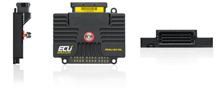
Type: Programmable Power Management Unit with Data Logging
Model: ECUMaster PMU24 DL
Manufacturer: ECUMaster
Product Page: ECUMaster PMU24 DL
Installation Manual: PMU User Manual v101.1.5 (PDF)
Pinout Diagram: PMU-24 Pinout v1.1 (PDF)
Wiring Diagram: See Installation Manual (pinout diagrams for PMU24)
Specifications
Outputs:
- 24 programmable high-side outputs (10×25A, 6×15A, 8×7A)
- Total capacity: 170A continuous (power supply limited, not sum of outputs)
- Constraint: Only same-rated outputs can be combined (e.g., 25A + 25A ✓, 25A + 15A ✗)
- Out 17-24: Dual-purpose - configurable as 7A outputs OR 0-20V analog inputs
Key Features:
- Dedicated 12V switched input (Pin 7), up to 16 analog inputs, 9 digital inputs
- 256MB data logger (500 Hz), real-time clock, IMU, inertia switch
- 2× CAN 2.0 A/B (J1939 compatible), 24× tricolor LED indicators
- PC config via USB (USB to CAN adapter required)
Physical: 131×112×33mm, 385g, -40°C to +125°C operating range
Grounding Note: PMU is high-side switching only - it switches the positive wire to loads. Each load must have its own ground path back to the battery/chassis. The PMU's ground connection (14 AWG) is only for internal electronics reference, not load current return. This is why PMU doesn't require a heavy ground wire matching the 2/0 AWG power feed.
Configuration Software: PMU Setup v101.2.1 | Full Specs: PMU Manual
Capacity Analysis
| Outputs | Rating | Total | Used | Available |
|---|---|---|---|---|
| 1-10 | 25A each | 10 | 5 | 5 |
| 11-16 | 15A each | 6 | 2 | 4 |
| 17-24 | 7A each | 8 | 8 | 0 |
| Total | - | 24 | 15 | 9 |
Utilization: 15 of 24 outputs used (63%) — 7 freed by relocating the radiator fan, iBooster, and TCU; OUT15 freed when the winch trigger was reallocated to BODY PDU CB43 (2026-05-30); OUT19 and OUT24 taken by the 4x4/4LO indicators (2026-09-18). The 7A bank (OUT17-24) is now full — future low-current loads go on the 15A bank.
Primary loads: HVAC (OUT5: ~20A load), GMRS radio (OUT6: ~15A load), aux cooling fans (OUT7+8: 2×15A), Dakota Digital (OUT9: ~25A), wipers (OUT11: 15A), CT4 (OUT13: ~9A), A/C clutch (OUT17: 7A), horn (OUT18: 7A), intercom (OUT20: 7A), brake lights (OUT21: 7A), reverse lights (OUT22: 7A), DRL/parking (OUT23: 7A), 4x4 indicator relay (OUT19: <0.2A), 4LO indicator (OUT24: <0.1A). Radiator fan (was OUT2+3+4), iBooster main + enable (was OUT1+10, OUT19), and Turbolamik TCU (was OUT16) relocated to the START+ Forward Distribution Bus; the winch contactor trigger (was OUT15) reallocated to BODY PDU CB43 — OUT1–4, 10, 15, 16, 19 now free.
Load: With the radiator fan, iBooster, and TCU relocated to the START+ Forward Bus, PMU peak drops to ~145A theoretical (all radios transmitting), ~85-115A typical continuous — comfortably within the 170A continuous PMU capacity. 7 outputs were freed by the fan/iBooster/TCU relocation and OUT15 by the winch-trigger reallocation; after the 4x4/4LO indicators took OUT19 and OUT24, 9 of 24 outputs are unassigned. The two indicator outputs are signal-level (<0.3A combined) and do not move the load figures.
Mounting: Engine bay, accessible for LED diagnostics and USB configuration
Related Documentation
- PMU Inputs - Input configuration and CAN bus integration
- PMU Outputs - 24-output configuration and load details
- PMU Programming - Logic examples and configuration
- START battery Distribution - PMU power source (2/0 AWG, 7 ft) and circuit breaker (250A)
- Wire Distance Reference - PMU to battery routing distance