2.9.1 HDX Control Module¶
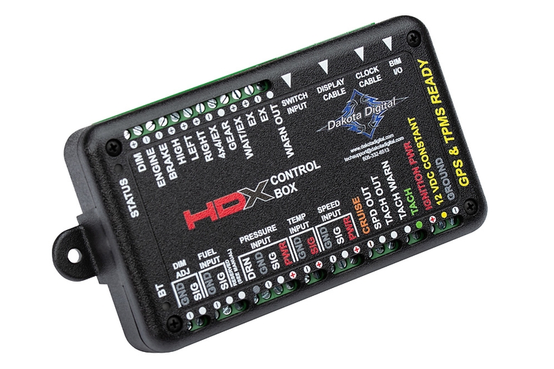
Type: Digital Instrument Control Box
Model: HDX Control Module (Black)
Manufacturer: Dakota Digital
Manual: HDX System Manual
Overview¶
Main control box for HDX instrument system. Processes sensor inputs, BIM module data, and J1939 CAN bus signals to drive dashboard cluster display.
Mounting: HDPE panel on firewall behind dashboard
Power: PMU OUT9 (25A capacity, CONSTANT power) — ⚠️ TBD #144 (architecture decision: PMU OUT9 vs Critical Cabin PDU Slot 2)
Specifications¶
- Dimensions: 5.5" W × 3.5" D × 1" H
- Power Input: 12V DC (8-23V operating range)
- Fuse Requirement: 5-20A max (per manufacturer specification)
- Recommended Fuse: 10A (adequate for entire HDX system including BIM modules)
- Current Draw: IGN Off ≈ 0.3mA, IGN On ≈ 250-750mA (confirms 10A fuse sizing)
- BIM Ports: 3.5mm headphone jack (supports up to 16 BIM modules via daisy-chain)
- Display Output: Proprietary cable to HDX dashboard cluster
- Configuration: Bluetooth app (iOS/Android) for setup and diagnostics
Input Signal Thresholds:
- Active High (HIGH, LEFT, RIGHT, GEAR, WAIT, DIM, EX+): Low ≤4V, High ≥8V
- Active Low (Check/ENGINE, BRAKE, CRUISE, 4x4, EX-): Low ≤8V, High ≥9V
- Tachometer: Normal mode 3-7.5V, Low-voltage mode 1-4V
- Speedometer: Square wave >1.2Vp-p or sine wave >1.4Vp-p
Output Capabilities:
- WARN, SPD outputs: <600mA max
Inputs¶
Included Sensors:
- Water temperature sender (100-260°F)
- Oil pressure sender (0-80 psi)
BIM Module Expansion:
- J1939 CAN bus interface (BIM-01-2-J1939)
- GPS speed/compass (GPS-50-2)
- TPMS (BIM-22-3)
- Compass/outside temp (BIM-17-2)
Fuel Level:
- Factory TJ fuel level sender (variable resistance)
Wiring¶
| Connection | Pin/Wire | Source | Destination | Notes |
|---|---|---|---|---|
| DIM ADJ - GND | - | - | - | Not used (dash dimming via DIM input instead) |
| DIM ADJ - SIG | - | - | - | Not used (dash dimming via DIM input instead) |
| FUEL INPUT - GND | - | Factory TJ fuel sender | HDX fuel GND | Sender ground |
| FUEL INPUT - SIG | 18 AWG ✓ | Factory TJ fuel sender | HDX fuel SIG | Variable resistance sender signal |
| PRESSURE INPUT - DRN | - | Included oil pressure sender | HDX pressure DRN | Included sensor - OR use J1939 oil pressure |
| PRESSURE INPUT - GND | - | Included oil pressure sender | HDX pressure GND | Included sensor - OR use J1939 oil pressure |
| PRESSURE INPUT - SIG | - | Included oil pressure sender | HDX pressure SIG | Included sensor - OR use J1939 oil pressure |
| PRESSURE INPUT - PWR | - | Included oil pressure sender | HDX pressure PWR | Included sensor - OR use J1939 oil pressure |
| TEMP INPUT - GND | - | Included water temp sender | HDX temp GND | Included sensor - OR use J1939 coolant temp |
| TEMP INPUT - SIG | - | Included water temp sender | HDX temp SIG | Included sensor - OR use J1939 coolant temp |
| SPEED INPUT - GND | - | - | - | Not used (GPS-50-2 provides speedometer via BIM) |
| SPEED INPUT - SIG | - | - | - | Not used (GPS-50-2 provides speedometer via BIM) |
| SPEED INPUT - PWR | - | - | - | Not used (GPS-50-2 provides speedometer via BIM) |
| CRUISE | - | - | - | Not used (no cruise control) |
| SPD OUT | - | - | - | Not used |
| TACH OUT | - | - | - | Not used |
| TACH WARN | - | - | - | Not used (J1939 provides tach via BIM-01-2) |
| TACH | - | - | - | Not used (J1939 provides tach via BIM-01-2) |
| IGNITION PWR | 16 AWG | Ignition bus bar | HDX ignition input | Switched 12V for ignition-controlled features |
| 12 VDC CONSTANT | 16 AWG ✓ | Critical Cabin PDU Slot 2 (⚠️ TBD #144) | HDX power input | 10A fuse, CONSTANT power, ~2 ft |
| DIM | 18 AWG ✓ | Tail light circuit | HDX DIM input | Dash dimming control (variable voltage) |
| ENGINE | 18 AWG ✓ | ECM Pin 22 (white wire, MIL) | HDX ENGINE input | Check engine light / MIL signal — sink-circuit (active low at wire) per Cummins R2.8 Installation Guide 5504137 |
| BRAKE | 18 AWG ✓ | Brake switch or CT4 | HDX BRAKE input | Brake pedal indicator |
| HIGH | 18 AWG ✓ | CT4 high beam output | HDX HIGH input | High beam indicator |
| LEFT | 18 AWG ✓ | CT4 left turn output | HDX LEFT input | Left turn indicator |
| RIGHT | 18 AWG ✓ | CT4 right turn output | HDX RIGHT input | Right turn indicator |
| 4x4/EX | 18 AWG ✓ | 4x4 relay contact (cabin), coil driven by PMU OUT19 | HDX 4x4 input | Ground-activated — green 4x4 indicator on Home Screen. Relay sinks the input because the PMU is high-side only. Active in 4H or 4L; sensing per Transfer Case (⚠️ TBD #145) |
| GEAR | - | BIM-01-2 J1939 | - | Gear position read from Turbolamik J1939 broadcast (no discrete input wiring) |
| WAIT/EX | 18 AWG ✓ | ECM Pin 35 (yellow wire, WAIT TO START) | HDX WAIT/EX input | Sink-circuit per Cummins R2.8 Installation Guide 5504137 (§2, ECM pin 35, yellow) — wire is active LOW (~0V when WAIT on, ~+12V when off). HDX input documented as "active high" — polarity bench-verification pending ⚠️ TBD #150. |
| EX (+) | 18 AWG ✓ | PMU OUT24 | HDX EXTRA(+) input | 12V-activated — custom label "4LO" (8 char max), active in 4L only (⚠️ TBD #145) |
| EX (−) | - | - | - | Reserved (ground-activated spare; fallback 4LO input if the sensor path is dropped) |
| WARN OUT | - | - | - | Not used |
| SWITCH INPUT | - | - | - | Not used (capacitive touch buttons on cluster) |
| DISPLAY CABLE | Proprietary | HDX control | Dashboard cluster | Factory harness included, ~2 ft |
| CLOCK CABLE | - | - | - | Not used (GPS-50-2 provides clock sync via BIM) |
| BIM I/O | Proprietary | HDX 3.5mm jack | BIM modules | Daisy-chain to 4 BIM modules (power + data) |
| Ground | 16 AWG ✓ | HDX ground | Critical PDU ground bus | Shared cabin ground, ~1 ft |
BIM Module Integration¶
All BIM modules connect via single daisy-chain harness from HDX control 3.5mm port:
- HDX Control → BIM-01-2-J1939 → GPS-50-2 → BIM-22-3 → BIM-17-2
- Power and data carried over BIM/IO cables (no separate power wiring)
- Modules auto-detect and configure via Bluetooth app
Outstanding Items¶
TBD tracker unavailable
Could not reach the GitHub issues API at build time (network or rate limit). Set GITHUB_TOKEN to raise the limit.
Build Tasks¶
- Determine brake indicator source (brake switch vs CT4 output)
- Install 4x4 relay near the HDX; coil ← firewall pin 19, contacts between HDX 4x4 terminal and Firewall Stud Bus ground
- Set the EXTRA(+) label to "4LO" in the HDX setup menu (8 char max)
- Verify indicators against actual lever position: 2H = no 4x4, 4H = 4x4 only, 4L = 4x4 + 4LO (⚠️ TBD #145)
- Bench-verify WAIT/EX polarity at HDX input — ⚠️ TBD #150: Cummins specifies active-low, HDX docs list "active high"; resolve before final wiring
Related Documentation¶
- Dakota Digital System Overview - Complete system architecture
- Dashboard Cluster - HDX display specifications
- BIM Modules - Expansion module details
- PMU Outputs - Power source (OUT9)
- Ignition Signal Distribution - Ignition power source
- Command Touch CT4 - Lighting signal sources (turn, high beam, etc.)
- Cummins R2.8 ECM - WAIT/EX (Pin 35 yellow) and ENGINE/MIL (Pin 22 white) signal sources
- Transfer Case - 4WD position sensing chain feeding the 4x4 and EXTRA(+) inputs