1.3.3 BODY PDU
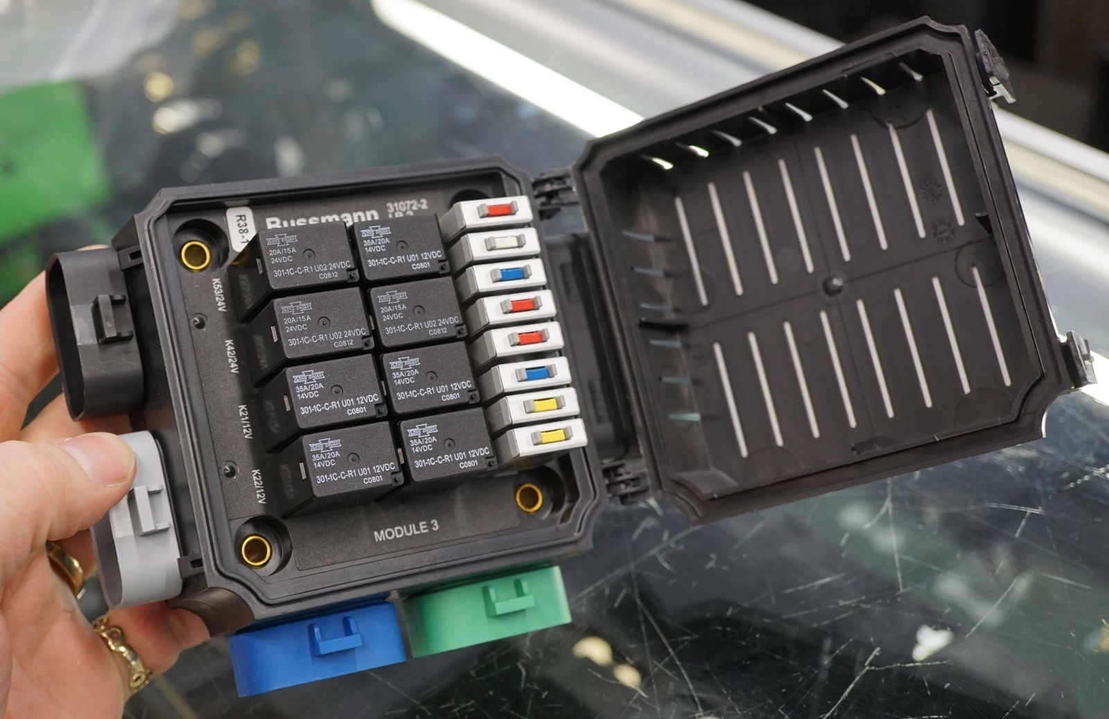
Type: Military-Spec Relay/Circuit Breaker Panel
Model: Bussmann LR-2
Part Number: Bussmann LR-2 panel, NSN 6110-01-523-6374 (the 301-1C-C-R1 is the Song Chuan ISO 280 relay that populates it, not the panel)1
Manufacturer: Bussmann (Eaton)
Source: Military surplus (MRAP/LMTV truck)
eBay Listing: Bussmann LR-2 Relay Breaker Block
Mounting: Firewall - body side (cabin), passenger side
Power Source: Firewall CONSTANT bus via 100A CB (2 AWG, ~2 ft local — bus is fed from AUX battery through a 250A MRBF terminal fuse at the AUX post and 2/0 AWG forward feed)
Ground: Firewall Stud Bus Terminal 3 (14 AWG) - relay coil/logic reference only
Configuration: 8 circuit breaker positions + 8 relay positions
Input: Military-spec power studs (accepts up to 2 AWG wire)
Output: J301-J306 Metri-Pack connectors (military-spec sealed)
Protection: IP65+ sealed military-grade enclosure
Temperature Rating: Military spec (-40°F to 221°F typical)
Voltage: 12V DC (originally 12V/24V dual voltage)
Circuit Breaker Configuration
| CB Position | Original Military Label | Repurposed Circuit | Size | Gauge | Load | Relay | Notes |
|---|---|---|---|---|---|---|---|
| CB30 | CHEM DETECT | Fusion Head Unit | 15A | 14AWG | ~15A | - | CONSTANT power, ignition sense from bus bar |
| CB48 | ARCT CRAN | USB Charging Ports | 20A | 14AWG | ~13A | - | 2x Powerwerx PanelUSB-75W (78W each, 7.5A fuse ea) |
| CB39 | TRLR BO STOP | WolfBox Camera/Mirror | 10A | 16AWG | ~10A | - | Dash cam + backup camera |
| CB45 | IGNITION | Driver Heated Seat | 10A | 14AWG | 5A peak, 2A sustained | K21 | Manual switch → relay K21 → seat element (dropped from 15A to match the 5A seat load, 2026-10-17) |
| CB42 | 2WAY INTRCM | Passenger Heated Seat | 10A | 14AWG | 5A peak, 2A sustained | K22 | Manual switch → relay K22 → seat element (dropped from 20A to match the 5A seat load, 2026-10-17) |
| CB20 | RADIO | Cargo Lights | 10A | 16AWG | 4A | - | Switch on rear wheel well top |
| CB43 | TRANS ECU | Winch Control (CH4X4 dual-push) | 10A | 18AWG | ~3A peak per direction | - | CH4X4-TOY-D-WINIO dual-momentary push at dash → HDP24 pins 16/17 → contactor; Warn remote parallel at contactor |
| CB44 | TRLR LIGHT | ARB Air Lockers (dash switches) | 10A | 18AWG | ~4A (~2A per solenoid) | K27 | K27 closes with the ignition; rear locker switch feeds the front switch (ARB interlock) — see Dashboard Controls |
Circuit Breaker Utilization: 8 of 8 used (0 available)
Relay Configuration
| Relay Position | Original Military Label | Repurposed Function | Voltage | Control | Notes |
|---|---|---|---|---|---|
| K21 | REAR LEFT LIGHT | Driver Heated Seat | 12V | Dash switch | Controls CB45 output to driver seat |
| K22 | REAR RIGHT LIGHT | Passenger Heated Seat | 12V | Dash switch | Controls CB42 output to passenger seat |
| K27 | TRAILER BO STOP | Air locker enable | 12V | Ignition bus Terminal 6 | Feeds CB44 to the locker switches only with the ignition on, so the lockers drop out at key-off |
| K30 | TRAILER REAR LEFT | [Available] | 12V | - | Future expansion |
| K31 | TRAILER REAR RIGHT | [Available] | 12V | - | Future expansion |
| K53 | RADIO | [Available] | 24V→12V | - | Swap 24V (U02) → 12V Song Chuan 301-1C-C-R1-U011 |
| K40 | START DISABEL | [Available] | 24V→12V | - | Swap 24V (U02) → 12V Song Chuan 301-1C-C-R1-U011 |
| K42 | ENGINE PTO | [Available] | 24V→12V | - | Swap 24V (U02) → 12V Song Chuan 301-1C-C-R1-U011 |
Relay Utilization: 3 of 8 used, 5 available (3 require 12V relay replacement)
Total Load: ~58A maximum (Radio 15A + USB 13A + Camera 10A + Seats 10A peak + Winch control 2A + Cargo lights 4A + Air lockers 4A)
Control: All circuits on CONSTANT power with trigger-wire or manual switch control for on/off, except CB44 (air lockers), which K27 enables only with the ignition on
Communication Devices
G1 GMRS Radio and STX Intercom are powered from the PMU — GMRS on OUT6, Intercom on OUT20 — with direct grounds to the START battery− to minimize RF noise. See PMU Outputs. SafetyHub is an AUX-side device and powers neither.
Outstanding Items
High (3)
- MRBF terminal fuse block and fuse part numbers (both battery posts) (#331) — The inline Mechanical Products Series 17 breakers at the START and AUX battery posts are being replaced by Blue Sea MRBF terminal fuses mounted on the posts (fewer lugs and joints). Confirm at order:
- START+ auxiliary distribution busbar + breakers for relocated fan / iBooster / TCU (#135) — Relocating the radiator fan, iBooster, and TCU from the PMU to START-battery-direct adds three breaker-protected feeds. All three loads are forward (engine bay / transmission) while the START battery is rear, so the chosen architecture mirrors the AUX forward-feed pattern: a single master-protected feed forward to an engine-bay busbar rather than three long runs or ~9 stacked lugs on the battery post.
- Dakota Digital Panel Mounting (#39) — HDPE sheet dimensions and location for the Dakota Digital panel.
📋 Medium (10)
- SwitchPros Output Wire Lengths (#107) — Wire lengths for the 12 SwitchPros SP-1200 output circuits (front/cabin/rear/roof fan-out from the firewall) are currently 'Various / TBD'. Determine once final load mounting locations are fixed.
- Radio Ground Routing (#82) — Path for 14 AWG ground wires from GMRS / Intercom (dashboard) to START battery negative (driver rear wheel well) - direct grounds required for RF noise isolation
- BODY PDU Metri-Pack Pinout (#69) — J301-J306 connector pinout (military TM or reverse engineering)
- Alternator Voltage Regulator Set Point (#68) — Verify 14.2-14.4V for AGM batteries
- Alternator Output Terminal Size (#67) — Terminal size for 1/0 AWG lug selection
- RF Power Grommet Location (#66) — Grommet 6 location near battery for radio power
- Roof/Roll Bar Routing (#64) — Light bars, dome lights
- Cab to Cargo Routing (#63) — Rear lights, compressor, lockers
- Dash to Console Routing (#62) — Switch panels, USB, radio
- Firewall Grommet Circuits (#61) — Complete wire bundle lists
📝 Low (1)
- AUX battery− chassis-bond (rear frame rail) peak return current (#124) — Peak current through the AUX battery− → rear frame rail 2/0 chassis bond needs a proper derivation.
🔍 Verify (2)
- ARB compressor feed length: reconcile 8/10/12 ft and measure (#154) — Three different lengths are documented for the SafetyHub → ARB twin compressor feed: ~8 ft (wire-distance reference), ~10 ft (harness inventory H6), ~12 ft (SafetyHub circuit table). The SafetyHub is in the passenger rear wheel well and the compressor under the seat, so the spread doesn't change the 6 AWG sizing materially, but the figure should be measured and unified across the three files.
- Measured cable distances: START battery → relocated radiator fan / iBooster / TCU (#136) — The radiator fan, iBooster main, and TCU now feed from the START+ forward distribution busbar (engine bay) via a single master feed from the START battery (driver rear wheel well). Provisional gauges:
Build Tasks
- Identify pinout for J301-J306 Metri-Pack connectors (military TM manual or reverse engineering)
Design Notes:
- High-side switching: BODY PDU switches positive power to loads; load current returns through each load's own ground wire, NOT through the PDU. The PDU ground connection (~3A) is only for relay coils and internal logic.
- Heated seat current: 5A peak, 2A sustained per seat (verified with vendor)
- Military relays K21/K22 provide fault isolation and independent operation
- J301-J306 connectors require custom harness fabrication
Related Documentation
- AUX battery Distribution - Power source and circuit breaker (passenger rear wheel well)
- Circuit Breakers - 100A CB protection for LR-2 power feed
- Dashboard Controls - Physical switch panel layout
- Audio Systems - Fusion radio specifications
- Firewall Ingress - Power feed routing through firewall
-
The Bussmann LR-2 is the panel;
301-1C-C-R1is the Song Chuan ISO 280 (2.8 mm) relay that populates it, voltage-coded by suffix — U01 = 12 V, U02 = 24 V. K40/K42/K53 ship with 24 V (U02); the 12 V drop-in is the same relay in U01 trim (301-1C-C-R1-U01-12VDC— SPDT, 35 A, ISO 280, resistor-suppressed). Sources: ProWire 301-1C-C-R1-U01-12VDC, eBay LR-2 listing (U01/U02 = 12 V/24 V); accessed 2026-06-06. ↩↩↩↩