1.6 Ignition Signal Distribution
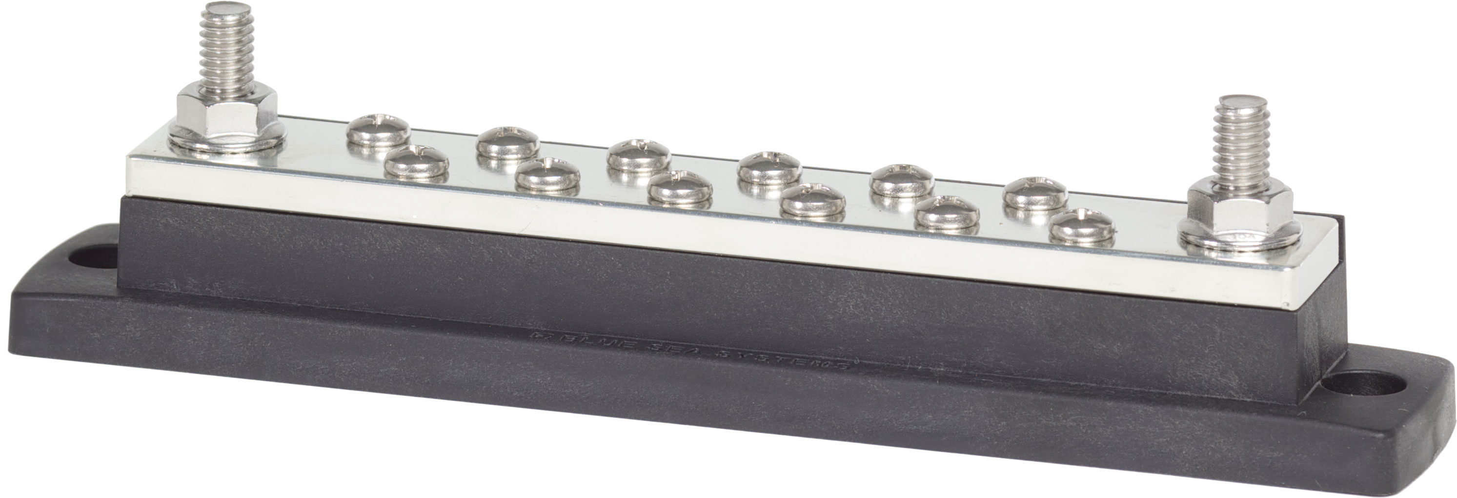
Type: Common BusBar
Model: Blue Sea 2105 MaxiBus
Manufacturer: Blue Sea Systems
Product Page: MaxiBus 250A BusBar
Overview
Distributes low-current 12V ignition sense signal to non-critical convenience devices. With the keyswitch removed (see Keyless Ignition), the bus bar input is now sourced from the PBS-I PINK IGN output (60A onboard relay inside the cabin-mounted PBS-I module). The PBS-I energizes PINK IGN whenever the system is in ACC (after 2 presses) or START mode; PINK does not drop during cranking.
Location: Cabin side of firewall
Function: Signal distribution only (not a power bus)
Engine-Bay Consumers Tap Through Firewall
The bus bar's outbound feed to engine-bay consumers (ECM 12V supply, PMU Pin 7) crosses the firewall on HDP24 Pin 12 — see Firewall Ingress.
- **PMU 12V Switched Input (Physical Pin 7):** Wire tapped from the bus bar engine-bay distribution stud - see [PMU Inputs][pmu-inputs]
- **Cummins ECM 12V Supply:** Wire tapped from the same engine-bay distribution stud
- **Turbolamik TCU wake:** Low-current tap from the same engine-bay distribution stud - see [Transmission][transmission]
- **iBooster Enable:** ~5A on its own ignition-bus terminal + **own 7.5A fuse** (not the ECM 5A feed) and its own firewall pin - see [Brake Booster][brake-booster]
- **Starter Control:** PBS-I PURPLE START output (separate firewall Pin 15) → Cole Hersee 24213 - see [Starter System][starter-system] and [Keyless Ignition][keyless-ignition]

**Note:** PMU "Pin 7" (physical connector pin for 12V switched power) is different from PMU "In 7" (digital input channel #7 used for CT4 headlight status).
Specifications
- Rating: 250A AC/DC continuous, 300V AC / 48V DC max
- Terminals: 12x #10-24 screws, 2x 5/16"-18 studs
- Dimensions: 7.93" L x 1.50" W
- Accessories: Insulating cover (Part 2718)
- Full Specs: Blue Sea 2105
Stud/Terminal Assignment
| Stud/Terminal | Connection | Wire Gauge | Distance | Max Current | Notes |
|---|---|---|---|---|---|
| Stud 1 (5/16") | PBS-I PINK IGN (INPUT) | 14 AWG ✓ | ~2 ft (cabin local) | ~5A total | No firewall crossing; PBS-I onboard 60A relay protects |
| Stud 2 (5/16") | Engine-bay outbound (OUTPUT) | 14 AWG ✓ | Through firewall (HDP24 Pin 12) | ~5A peak | 5A inline fuse required at this stud per Cummins R2.8 install manual; feeds ECM Pin 41 (black, keyswitch) + PMU Pin 7 + Turbolamik TCU wake (low current) |
| Terminal 1 (#10-24) | Command Touch CT4 | 18 AWG ✓ | ~3 ft | ~20mA | Ignition sense for turn signal auto-cancel |
| Terminal 2 (#10-24) | SwitchPros SP-1200 | 18 AWG ✓ | ~4 ft | ~20mA | Pin 3 (Lt Blue) - ignition sense |
| Terminal 3 (#10-24) | Fusion MS-RA670 Radio | 18 AWG ✓ | ~2 ft | ~20mA | Yellow wire - ignition sense |
| Terminal 4 (#10-24) | BCDC Alpha 50 | 18 AWG ✓ | ~12 ft | ~20mA | Blue wire - activates charging when engine running |
| Terminal 5 (#10-24) | iBooster Enable | 16 AWG ✓ | ~10 ft (own HDP24 pin) | ~5A | iBooster ignition enable; own 7.5A inline fuse (not shared with the ECM 5A feed); crosses firewall |
| Terminals 6-12 (#10-24) | [Available] | - | - | - | Future expansion (7 terminals) |
Utilization: 7 of 14 used (2 studs + 5 terminals used, 0 studs + 7 terminals available)
Mounting
Location: Cabin side of firewall, behind dash (former keyswitch location now repurposed)
Benefits: PBS-I source is local (cabin), most consumers are cabin-side; single outbound firewall feed (Pin 12) serves engine-bay loads
Related Documentation
- Power Systems Overview
- PMU Inputs - Pin 7 ignition sense and signal distribution diagram
- Firewall Ingress - Grommet 2 specifications
- BCDC Alpha 50 - Charging activation