8.2 Air Compressor
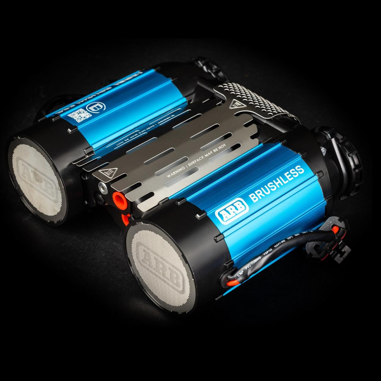
ARB Twin Compressor system with air tank and automatic pressure management for locker operation and tire inflation.
Model: ARB CKBLTA12 Brushless Twin Motor Onboard 12V Air Compressor
Status: Purchased
Product Page: ARB CKBLTA12
Installation Guide: ARB CKBLTA12 Installation PDF
Maximum Amperage Draw: 90A total (45A per motor × 2 motors)1
Fuse Configuration: Dual 60A MIDI fuses via SafetyHub 150 (one per motor)1
Location: Under passenger seat
Product Image:
Specifications
| Spec | Value |
|---|---|
| Motor Type | Brushless, twin motor |
| Voltage | 12V |
| Max Amperage | 90A total (45A per motor) |
| Duty Cycle | 100% |
| Maximum Pressure | 150 PSI |
| Air Flow @ 0 PSI | 9.18 CFM |
| Air Flow @ 29 PSI | 6.20 CFM |
| Cooling | Active cooling with built-in fans |
| Smart Start | Staggered motor power-on |
| Electronic Control | Speed control for temp/pressure |
| IP Rating | IP67 water resistant |
| Dimensions (L×W×H) | 14.49" × 13.31" × 6.69" |
| Weight | 15.8 lb (complete), 13.2 lb (bare) |
| Warranty | 3 years |
Control System
SwitchPros OUTPUT-11 (Button 11) provides a switched 12V control signal; the compressor's internal relay handles the high-current motor switching, so only a light 14 AWG control wire is needed alongside the 6 AWG motor power/ground (see Wiring table below).
Wiring
| Circuit | Source | Destination | Wire | Protection | Notes |
|---|---|---|---|---|---|
| Motor 1 Power | SafetyHub MIDI-1 (60A) | Compressor motor 1 positive | 6 AWG | 60A MIDI | Via SafetyHub 150A CB |
| Motor 2 Power | SafetyHub MIDI-2 (60A) | Compressor motor 2 positive | 6 AWG | 60A MIDI | Via SafetyHub 150A CB |
| Ground | Compressor negative terminal | AUX battery negative | 6 AWG | None | Direct for 90A return current |
| Control | SwitchPros OUTPUT-11 | Compressor control terminal | 14 AWG | 15A | Auto or manual activation |
Air Tank
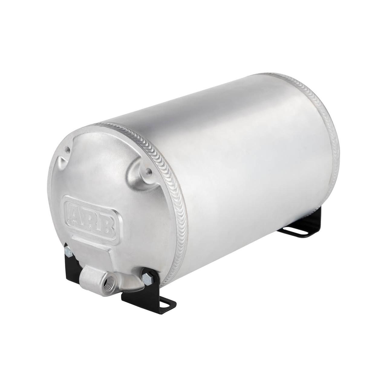
ARB 1-Gallon Air Tank
Model: ARB 171507 (Aluminum, 1-gallon, 4-port)
Status: To purchase (targeting 1-gallon capacity)
Product Page: ARB 171507 Aluminum 1-Gallon Air Tank
Product Image:
| Spec | Value |
|---|---|
| Capacity | 1 gallon (4 liters) |
| Working Pressure | 150 PSI maximum |
| Material | Forged aluminum end caps + extruded aluminum body (~50% lighter than steel) |
| Mounting | Under passenger seat (horizontal or vertical) |
| Ports | 4 × 1/4" NPT (daisy-chain compatible) |
Pressure Switch
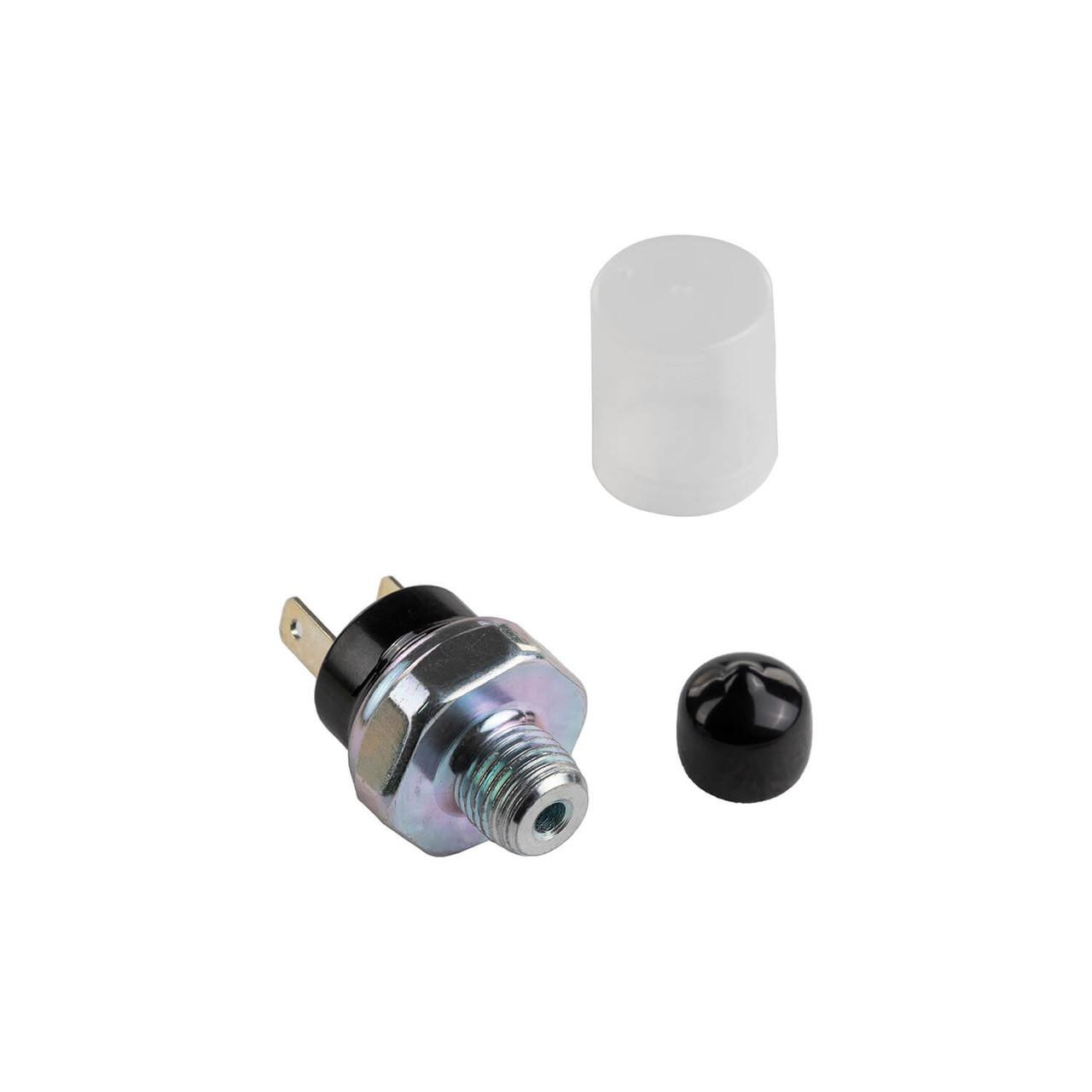
ARB Pressure Switch
Model: ARB 180901
Status: Purchased
Product Page: ARB Pressure Switch
Product Image:
| Spec | Value |
|---|---|
| Cut-In Pressure | 135 PSI (compressor starts) |
| Cut-Out Pressure | 150 PSI (compressor stops) |
| Mounting | On air manifold |
| Electrical | Low-current switch (<1A) |
Air Manifold
Configuration: 4-6 port brass manifold
Status: Purchased
Location: Under passenger seat (with compressor and tank)
Port Assignments:
- Input: Compressor output → manifold input
- Output 1: Manifold → Front locker solenoid (1/4" air line)
- Output 2: Manifold → Rear locker solenoid (1/4" air line)
- Output 3: Manifold → Rear Air Chuck Plate (1/4" air line)
- Output 4: Manifold → Pressure gauge (0-200 PSI, panel-mounted)
- Output 5: Manifold → Pressure switch (ARB 180901)
Automatic Pressure Control
SwitchPros Integration
Button 11 OR TRIGGER-3 → OUTPUT-11 (compressor). See SwitchPros TRIGGER-3 section for full programming logic.
Operational Modes:
| Mode | Control Method | Use Case |
|---|---|---|
| Automatic | Pressure switch via TRIGGER-3 | Normal operation - system maintains pressure automatically |
| Manual Override | Button 11 (latching mode) | Tire inflation - keep compressor running continuously |
| Off | Button 11 off + tank > 135 PSI | Compressor idle, tank maintains pressure for locker use |
Pressure Switch Wiring
| Circuit | Source | Destination | Wire | Protection |
|---|---|---|---|---|
| Pressure Switch Trigger | Pressure switch signal terminal | SwitchPros TRIGGER-3 (Pin 17) | 18 AWG | None (low current) |
Outstanding Items
TBD tracker unavailable
Could not reach the GitHub issues API at build time (network or rate limit). Set GITHUB_TOKEN to raise the limit.
Build Tasks
- Verify ARB CKBLTA12 wiring harness connector pinout for motor 1, motor 2, and control terminals
- Confirm under-seat mounting bracket/location for compressor and 1-gallon tank
- Purchase ARB 171507 1-gallon aluminum air tank
- Order 0-200 PSI pressure gauge (panel-mount or in-line)
Related Documentation
- Air Lockers - ARB RD166 front / RD140 rear lockers
- Rear Air Chuck - External air access plate
- SafetyHub - Compressor power distribution
- SwitchPros - Compressor control (OUTPUT-11, TRIGGER-3)
-
ARB publishes Max Amps 90 (total) for the CKBLTA12 brushless twin — matches our doc. The 45A per motor is the 90÷2 split (ARB does not publish a per-motor figure), and the 60A MIDI fuse per motor is this build's protection choice (not an ARB-specified value), sized above the ~45A per-motor draw. Source: ARB CKBLTA12 product page (checked 2026-05-30). NB: this is the brushless CKBLTA12 — do not apply specs from the older brushed CKMTA12 (28A/50A, 40A fuse), which is a different unit. ↩↩