Section 2: Diagrams
Every drawing on this page is a page of Van Electrical.drawio at the
repository root. The draw.io file is the source of truth - these PNGs are
regenerated from it by the drawio-export workflow, so edit the drawing, never
the image.
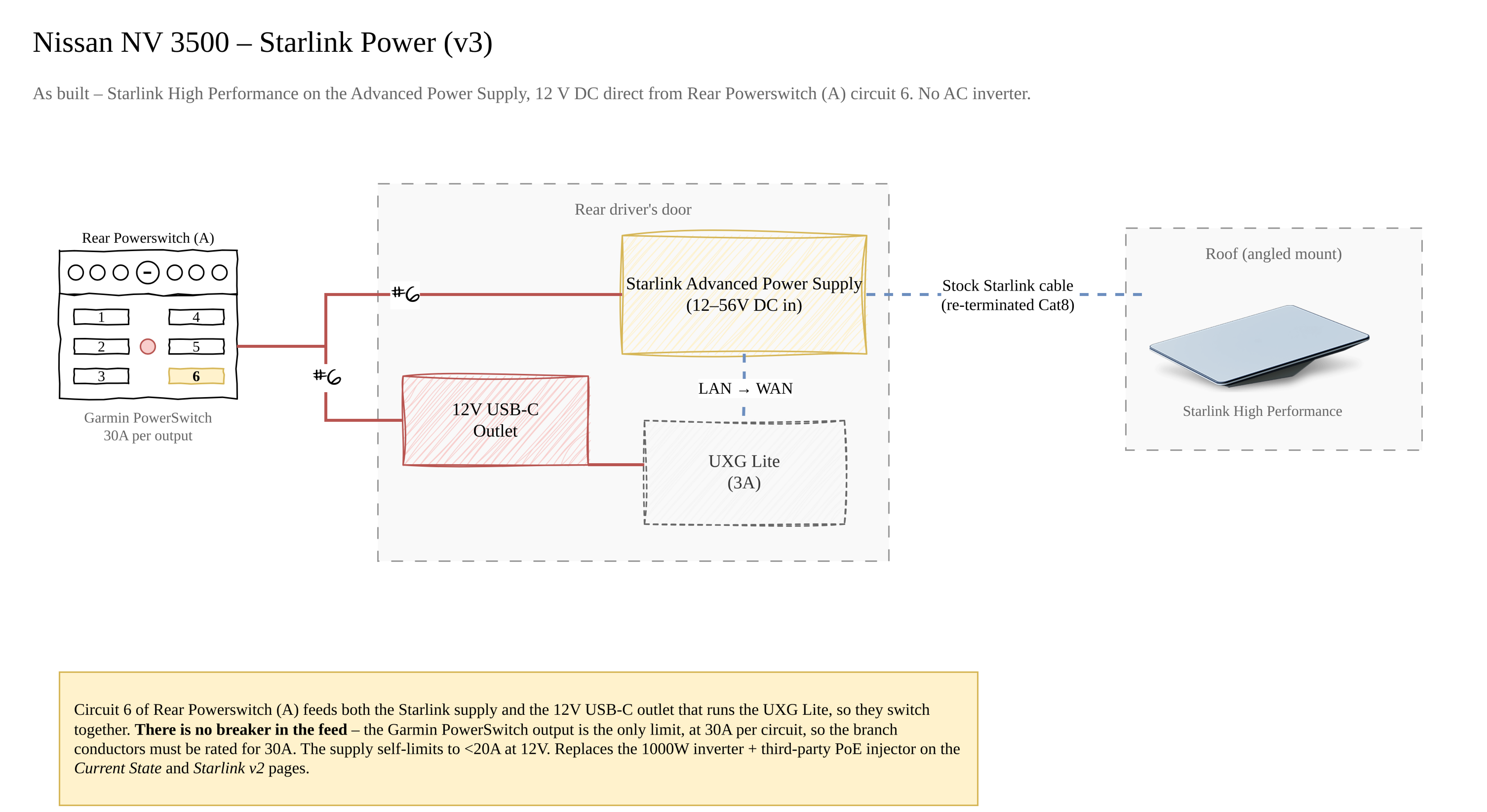
Starlink Power (v3)
The Starlink feed as built: Rear Powerswitch (A) circuit 6 → Starlink Advanced Power Supply → High Performance dish, on 12 V DC with no inverter. The same circuit triggers the 12 V USB-C outlet that runs the UXG Lite, and the supply's LAN port feeds the UXG Lite WAN input. Written up in Starlink Power.
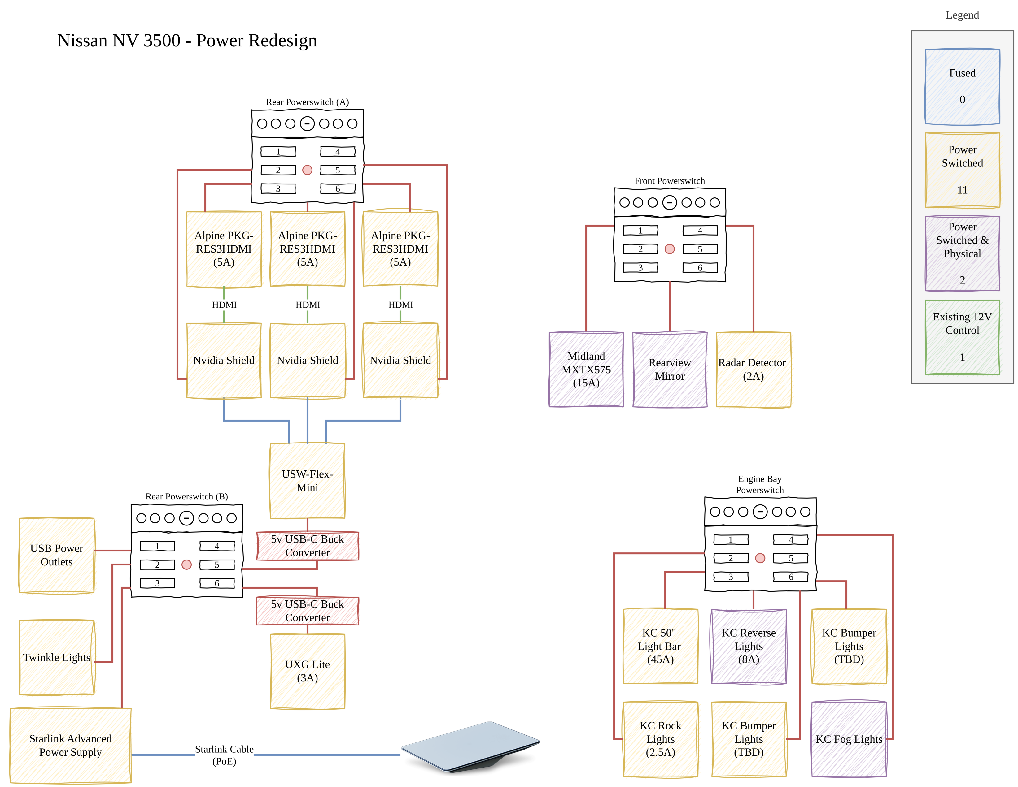
Devices
Device-level view of the power redesign: all four Powerswitch panels and everything hanging off them, with the legend counting how each load is controlled.
This is the plan, not the as-built
The redesign groups Starlink and the UniFi gear on Rear Powerswitch (B) and includes a USW-Flex-Mini switch. As built, Starlink and the UXG Lite are on Rear Powerswitch (A) circuit 6 and there is no Ethernet switch - see Starlink Power.
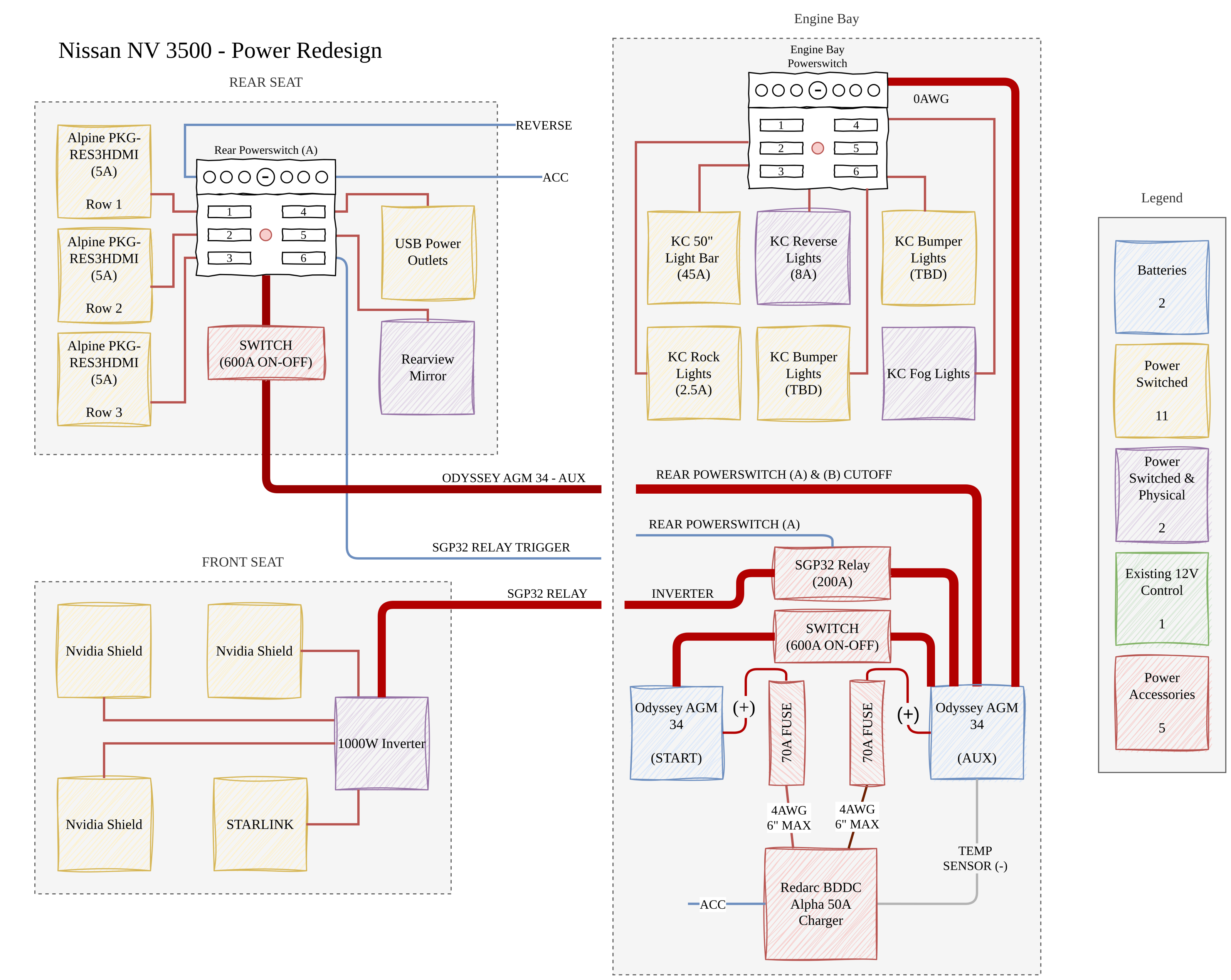
Current State
The system as originally wired, including the 1000 W inverter that Starlink was powered through. Kept as the before picture - the Starlink branch shown here is superseded by Starlink Power.
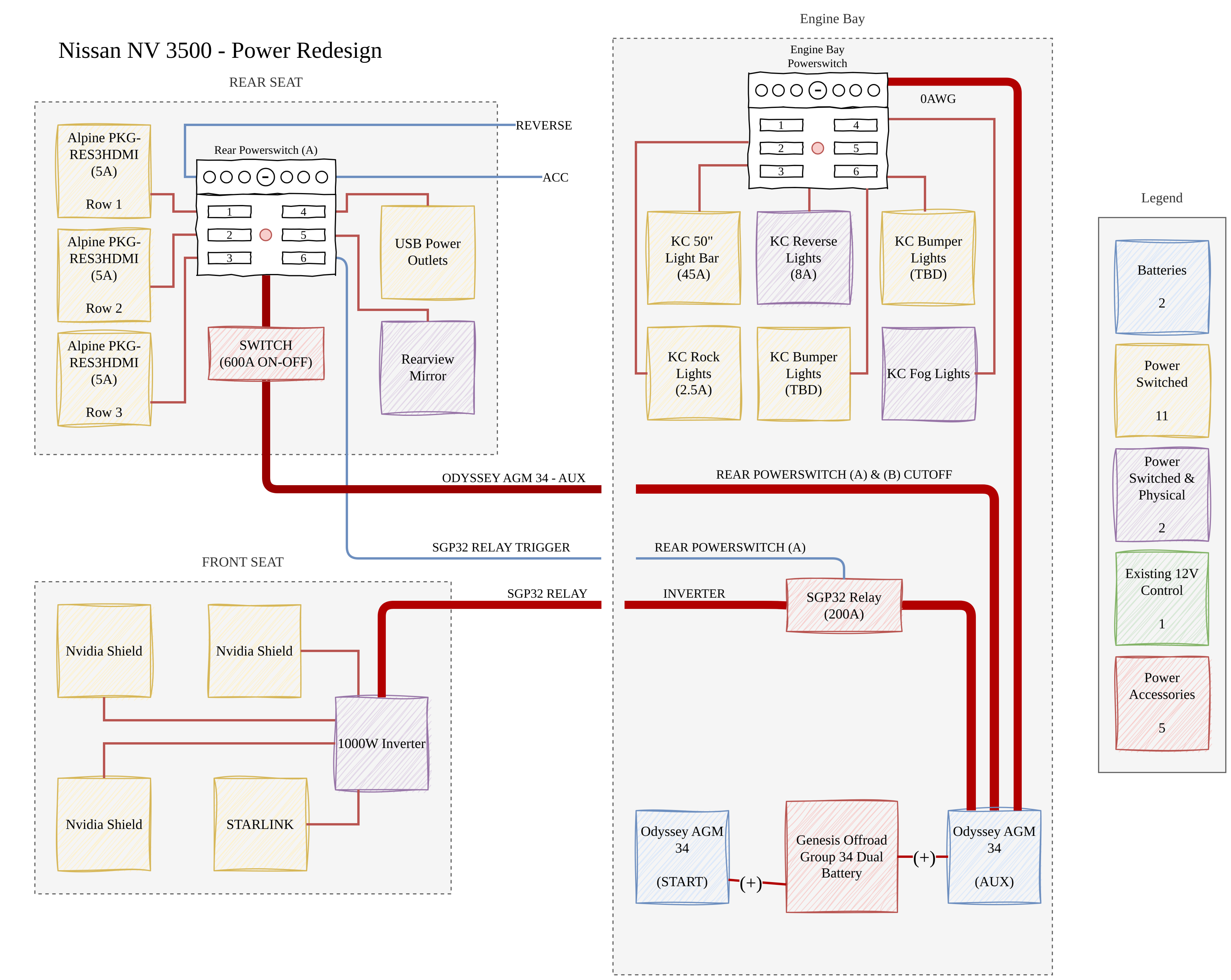
Genesis
A variant of the same system using a Genesis Offroad Group 34 dual-battery tray in place of the discrete START/AUX arrangement with the BCDC charger. Recorded as an option that was considered; see the Outstanding Items in Power Systems.
Superseded pages
Van Electrical.drawio also carries a Starlink v2 page - the Yaosheng PoE
injector approach that preceded the Advanced Power Supply. It is kept in the
drawing for history but is not rendered here.