1.1 Starlink Power
The original Starlink High Performance dish runs off a Starlink Advanced Power Supply fed directly from the van's 12 V DC system. This replaces the 1000 W AC inverter the dish was originally powered through, and closes #4.
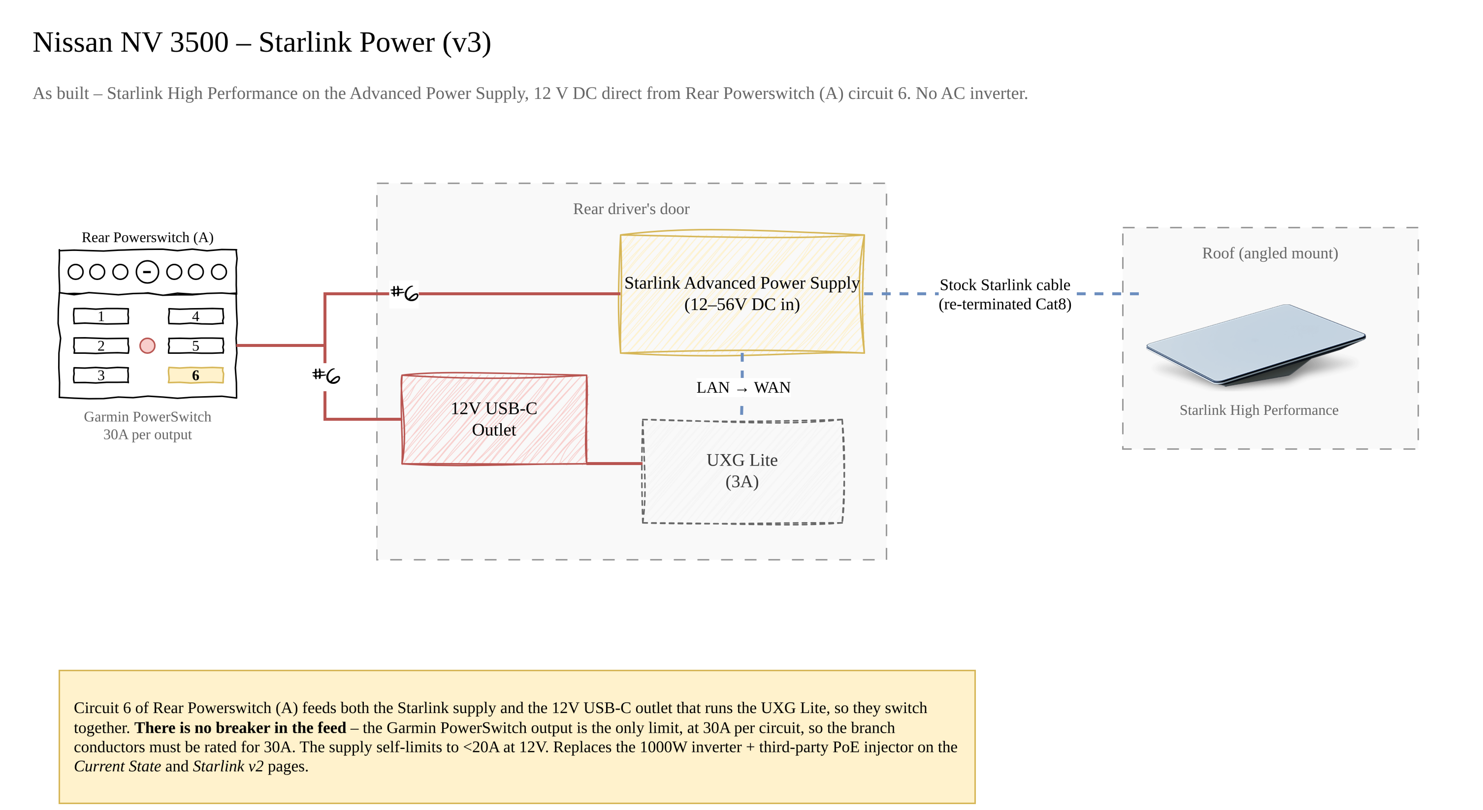
Diagram source: Van Electrical.drawio (page "Starlink v3"); the image is regenerated from the draw.io file on each export.
Why this replaced the inverter
The original install ran 12 V → 1000 W inverter → 120 V AC → the Starlink AC brick → PoE to the dish. Two DC/AC/DC conversions in series, with the inverter sitting idle-drawing whenever Starlink was on.
The alternatives worked through in #4 were all worse:
| Option | Why it was dropped |
|---|---|
| Keep the inverter | Conversion losses and inverter idle draw; the thing it was there for is now solved upstream |
| 24 V or 48 V sub-bank for the dish | Needs a second battery chemistry/voltage in the van, its own DC-DC charger, and re-plumbing everything else to 24 V |
| Generic step-up PoE injector | The PoE injector documentation calls for a high-quality supply; unbranded 12→48 V buck/boost injectors were not trusted at 320 W |
| Starlink Advanced Power Supply | Takes 12 V DC natively, is the vendor's own part, and drops both the inverter and the third-party injector out of the path |
Advanced Power Supply
| Spec | Value | Source |
|---|---|---|
| Input | 100-240 V AC or 12-56 V DC | Starlink Performance spec sheet |
| DC certified range | 10.5-57 V DC | Starlink support |
| Recommended DC input | Above 20 V where available | Starlink support |
| DC current limit | Self-limits to under 20 A; output power is reduced at low input voltage to stay there | Starlink support |
| Ports | High-power PoE (to the dish) + LAN | Starlink Performance spec sheet |
| Dimensions | 310 x 180 x 40 mm (12.2 x 7.1 x 1.6 in) | Starlink Performance spec sheet |
| Weight | 2.1 kg (4.6 lb) | Starlink Performance spec sheet |
| Environmental | IP68 with cables installed, -40 °C to 60 °C | Starlink Performance spec sheet |
| DC cable supplied | Starlink DC Power Cable, 1.5 m, 2-pin (red +, black −) | Starlink Performance spec sheet |
12 V is the bottom of the useful range
Starlink certifies the supply down to 10.5 V but recommends staying above 20 V. On a 12 V bank the supply caps itself at under 20 A, so peak delivery is roughly 240 W before conversion losses. That covers a dish averaging 75-100 W, but snow-melt and high-throughput peaks are exactly the conditions where the supply will throttle. An AGM bank sagging toward 11.5 V under load gives away more headroom still.
If Starlink performance turns out to be capped in cold weather, the fix is a higher input voltage (a 24 V sub-bank on a DC-DC charger), not a bigger 12 V feed.
Circuit
The supply is switched from Rear Powerswitch (A), circuit 6 - a Garmin PowerSwitch. That circuit is shared: it also triggers the 12 V USB-C outlet in the rear driver's door, which is what powers the UniFi UXG Lite.
| Item | Value |
|---|---|
| Source | Rear Powerswitch (A), circuit 6 (Garmin PowerSwitch) |
| Shares the circuit with | 12 V USB-C outlet (rear driver's door) → UXG Lite (3 A) |
| Nominal system voltage | 12 V DC |
| Overcurrent protection | No separate breaker. The Garmin PowerSwitch output is the limit: 30 A max per output, 100 A max system (Garmin specs) |
| Expected draw | Up to ~20 A - the supply's own self-limit at 12 V - plus the USB-C outlet |
| Supplied DC cable | Starlink DC Power Cable, 1.5 m, 2-pin (red +, black −) |
| Output to dish | Stock Starlink cable, cut and re-terminated with a Cat8 connector |
| LAN port | → UXG Lite WAN input |
Circuit 6 carries two loads and they switch together
Because the Starlink supply and the 12 V USB-C outlet share circuit 6, killing Starlink at the panel also kills the UXG Lite - the gateway and the uplink drop together. That may be exactly what you want; it is worth knowing it is not two independent switches.
Protection comes from the PowerSwitch, not a breaker
There is no inline breaker on the circuit 6 run. The Garmin PowerSwitch caps each output at 30 A, which is what protects the branch. That is comfortably above the supply's ~20 A self-limit plus the USB-C outlet, so the arrangement works - but it means the wire from the PowerSwitch to the supply must itself be rated for 30 A, since that is the most the output will pass before shutting down. Size the conductor to the output rating, not to the expected draw.
Physical layout
| Item | Location |
|---|---|
| Starlink High Performance dish | Roof, mounted at an angle |
| Starlink Advanced Power Supply | Rear driver's door, directly above the UXG Lite |
| UXG Lite | Rear driver's door |
| 12 V USB-C outlet | Rear driver's door |
Everything except the dish lives in the rear driver's door, which is why the diagram groups them into one zone: the supply, the gateway it uplinks, and the outlet that powers the gateway are all within reach of each other. The only run leaving the door is the dish cable to the roof.
What this removes
Both of these come out of the Starlink path:
- 1000 W inverter - still shown on the Current State and Genesis diagrams, which document the system as it was before this change. It may still be wanted for other AC loads; that is a separate decision.
- Third-party PoE injector - the Yaosheng 8 A injector, shown on the superseded "Starlink v2" page. The dish cable is now the stock Starlink cable, cut and re-terminated with a Cat8 connector so it lands properly on the supply's PoE port.
Outstanding Items
- Measure real-world draw at 12 V (idle, streaming, snow melt) and record it here
- Record the wire gauge and run length for the circuit 6 feed - it must be rated for the PowerSwitch's 30 A output, not just the expected draw
- Confirm the fuse on the Garmin PowerSwitch's own battery feed (Garmin's manual references a 125 A fuse on the supplied red power cable)
- Confirm the re-terminated dish cable is wired to Starlink's pinout, and record its run length from the door to the roof mount