2.10 ADU7 Supplemental Display
ECUMaster ADU7 auxiliary display for engine and electrical system metrics not covered by Dakota Digital HDX.
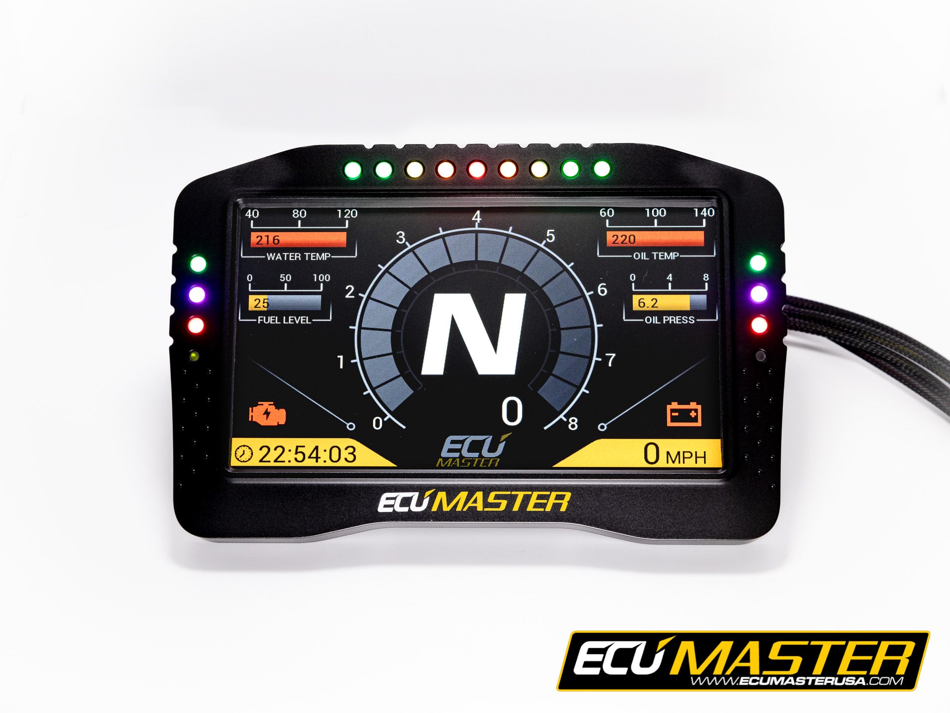
Type: Advanced Display Unit
Model: ADU7 Rev 2 (IP65)
Manufacturer: ECUMaster
Product Page: ECUMaster ADU7
Mounting: A-pillar cage (driver side)
Power Source: PMU OUT14 (15A, SWITCHED)
Specifications
| Spec | Value |
|---|---|
| Display | 7" TFT |
| Resolution | 800 x 480 |
| Rating | IP65 |
| CAN Interfaces | 2× CAN 2.0B |
| CAN Speeds | 250, 500, 1000 kbps |
| Power Draw | ~1-2A |
Purpose
Supplemental display for metrics the Dakota Digital doesn't show well:
| Data | Source | Notes |
|---|---|---|
| Boost pressure | PMU An 5 | 0-5V transducer |
| EGT | PMU An 6 | Thermocouple + amplifier |
| START battery voltage | PMU internal | Already monitored |
| AUX battery voltage | PMU An 7 | Voltage divider |
| PMU output currents | PMU internal | Per-channel monitoring |
| PMU faults/warnings | PMU internal | Overcurrent, thermal |
| Oil temp | PMU via J1939 | Pass-through from Cummins |
| Coolant temp | PMU via J1939 | Pass-through from Cummins |
Integration
Cummins ECM ──J1939──► PMU24 ──ECUMaster CAN──► ADU7
                         │
              Analog sensors (boost, EGT, trans temp, AUX voltage)
- PMU24 reads J1939 engine data and analog sensor inputs
- PMU24 broadcasts on ECUMaster CAN protocol
- ADU7 receives natively - same manufacturer, no custom templates
Wiring
| Connection | Wire | Source | Notes |
|---|---|---|---|
| Power (12V) | 16 AWG | PMU OUT14 | SWITCHED with ignition |
| Ground | 16 AWG | TBD | A-pillar ground point |
| CAN H | 20 AWG | PMU24 CAN 2 | ECUMaster protocol |
| CAN L | 20 AWG | PMU24 CAN 2 | Twisted pair with CAN H |
Outstanding Items
- Confirm PMU24 CAN output configuration for ADU7 data
- Determine A-pillar ground point location
- Select boost pressure transducer (0-5V, range TBD based on expected boost)
- Select EGT probe and amplifier
- Design AUX battery voltage divider circuit for PMU analog input
- Configure ADU7 display pages/layout
- Route CAN wiring from PMU (firewall) to A-pillar
Related Documentation
- PMU Inputs - Analog input configuration
- PMU Outputs - OUT14 power source
- Dakota Digital HDX - Primary gauge cluster